About AFM
The idea of using a sharp probe to image and manipulate surfaces at the atomic level dates back to the late 1950s and early 1960s, with the pioneering work of G. Binnig and H. Rohrer, who later received the Nobel Prize in Physics for their inventions. However, the first practical AFM was not developed until the late 1980s, when it was invented independently by three research groups: one led by Gerd Binnig and Calvin Quate at IBM, the other led by Gerd Binnig and Calvin Quate at IBM Christopher Gerber and Art Heinrich at Stanford University came first and third. led by Alain Marti and Michel Orrit at the University of Leiden.
Principles of atomic force microscopy
Using a micro-machined silicon probe with a very small tip, the AFM microscope performs surface sensing. A line-by-line raster of the sample's surface is how this trick is used to create the image, although the specifics of how to do this vary considerably across different modes of operation. Exposure mode and dynamic mode, sometimes called mining mode, are the two main types of operating modes.
AFM works on the premise that this nano-sized tip is connected to a small cantilever, which acts like a spring. There is a laser diode and a photodetector to detect bending of the cantilever when the tip is in contact with the surface. The force exerted by the tip of the tip on the specimen in this bend can be seen. The contact mode involves pressing the tip against the surface while the electrical feedback loop measures the force of interaction between the tip and the sample to maintain a constant deflection throughout the raster scan.
Tapping mode reduces initial contact time with the sample surface to ensure both surface and tip integrity. When operating in this mode, the cantilever is excited to vibrate very close to its natural resonant frequency. Then the tip moves up and down in a sinusoidal motion. As this motion approaches the sample, it is slowed down by attractive or repulsive interactions. When in contact mode, a feedback loop maintains a constant standard deviation; here, a feedback loop maintains a constant amplitude for the knocking motion. So doing so is like drawing a geographic map of the sample.
Working principle:
Similar to STM, a tip is rasterized across the surface as a feedback loop fine-tunes the image parameters. Atomic force microscopes, as opposed to scanning tunneling microscopes, do not require conductive materials. Atomic forces are used to create a map of head-sample interactions rather than the quantum mechanical effects of tunneling. Atomic force microscopy (AFM), also known as scanning probe microscopy (SPM), can be used to measure practically any measurable force interaction, including van der Waals forces, electric, magnetic and thermal forces. Software tuning and advice tuning are necessary for some of the more specific methods.
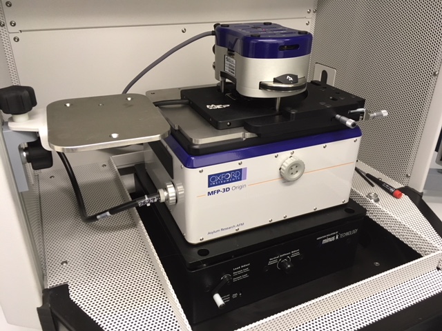
An illustration of an atomic force microscope model Oxford firm
Atomic force microscopy (AFM), also known as scanning probe microscopy (SPM), can be used to measure practically any measurable force interaction, including van der Waals forces, electric, magnetic and thermal forces. Software tuning and advice tuning are necessary for some of the more specific methods.
Common in AFM is a laser beam deflection mechanism that works by bouncing a laser beam off the reflector of the AFM and into a position-sensitive detector. Both the AFM head and cantilever are typically micro-fabricated from Si or Si3N4. Typical tip radii range from a few nm to tens of nm.
Laser beam deflection for atomic force microscopy
When photographing with AFM, the forces between the tip and the sample cannot be ignored because they are the basis of the technique. Instead of directly measuring the force, we can infer it from the deflection of the lever by knowing the stiffness of the cantilever.
Applying Hooke's law, we get:
F = -kz
where F is the force, k is the stiffness of the lever and z is the bend of the lever.
Force-distance curves for atomic force microscopy
- Feedback loop for atomic force microscopy
A feedback loop based on laser deflection adjusts the force and tip position of the atomic force microscope. The AFM head is attached to a cantilever and the laser is reflected off the back of the cantilever. The position of the laser on the photodetector is fed back into the loop to track the surface and take readings as the tip moves over it. Diagram for Atomic Force Microscopy exposure mode